Conducted Immunity Test(CI)是一種用於評估電子設備抗導電干擾能力的測試方法。導電干擾通常是由於其他電氣設備或線路所產生的電氣噪聲引起的。CI 測試可以確保設備能夠在導電干擾下正常運行,並且不會對其他設備造成干擾。
在進行 CI 測試時,測試人員會使用導電干擾發生器來產生導電干擾信號,並將這個信號傳遞到待測設備上。待測設備會在導電干擾下進行操作,而測試人員會監測設備是否能夠正常運行。
在 CI 測試過程中,測試人員會使用不同的測試參數,例如導電干擾發生器的頻率、幅度、波形等。這些參數通常是由相關的 EMC 標準和規定所指定的。
通過 CI 測試,可以確定設備能夠承受導電干擾的強度和頻率範圍,以及設備在受到導電干擾時是否能夠正常運行。這些測試可以幫助設計人員和製造商確保其產品符合相關的 EMC 標準和規定。
總之,CI 測試是一種用於評估電子設備抗導電干擾能力的測試方法,通過模擬導電干擾信號來確定設備能夠承受導電干擾的強度和頻率範圍,以及設備在受到導電干擾時是否能夠正常運行,以確保設備符合相關的 EMC 標準和規定。
The purpose of this standard is to test the conducted immunity requirement of electrical and electronic equipment to electromagnetic disturbances coming from intended RF transmitters in the 9 kHz to 80MHz frequency range. Equipment that does not have at least one conducting cable that can couple equipment to the disturbing RF field is excluded from this requirement.
The object of this test is to establish a common reference for evaluating functional immunity when subjected to conducted disturbances.
The source of the disturbance is basically an electromagnetic field coming from intended RF transmitters that may have an effect on the cables connected to the equipment under test. This test is needed because untested cables can behave as passive receiving antenna networks and affect the performance of the equipment. Susceptible equipment is exposed to currents flowing through the equipment. Cable systems connected to the equipment are assumed to be in resonant mode, and as such are represented by coupling and decoupling devices having a common mode impedance of 150Ω with respect to the ground reference plane. When possible, the equipment is tested by connecting it between two 150Ω common mode impedance connections; one providing an RF source and the other providing a return path for the current. The test method in this standard subjects the EUT to a source of disturbance comprising electric and magnetic fields, which simulate those fields coming from intentional RF transmitters.
Test Equipment
Test Generator – includes all equipment and components for supplying the input port of each coupling device with the disturbing signal at the required signal level. The test generator must contain the following:
RF generator (G1) – must be capable of covering frequency band of interest and being amplitude modulated by a 1 kHz sine wave with modulation depth of 80%.
Attenuator (T1) – typically 0dB to 40dB, of adequate frequency rating to control output level. May be included in RF generator
RF switch (S1) – used to switch signal on and off, may be included in RF generator
Broadband Power Amplifier (PA) (Optional) – if necessary will be used to amplify signal if output power is insufficient.
Low Pass/High Pass Filters (Optional) – may be necessary to avoid interference caused by harmonics with some types of EUT’s. When required, should be inserted in between amplifier and attenuator (T2)
Attenuator (T2) – Fixed ≥6dB, Z₀ =50Ω; with sufficient power ratings, this is provided to reduce a mismatch from power amplifier and coupling device
Characteristics of test generator
• Output impedance = 50Ω
• Harmonics and Distortion = at least 15dB below carrier level
• Amplitude modulation = internal or external; 80%±5% in depth; 1 kHz sine wave ±10%
• Output level = sufficient to cover test level
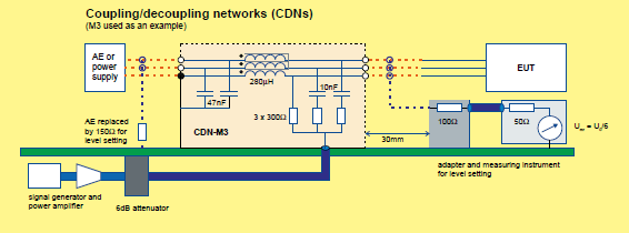
Coupling and Decoupling Devices – The appropriate coupling of the disturbing signal to the various cables connected to the EUT can be achieved through either the use of separate coupling and decoupling devices or the more preferred method of using a Coupling/Decoupling Network (CDN). CDN’s are preferred because of their test reproducibility and protection of the Auxiliary Equipment (AE).
CDN’s or coupling and decoupling devices must adhere to the following parameters:
CDN’s are comprised of the coupling and decoupling circuits in one box and can be used for specific unscreened cables. CDN’s are recommended for power supply connections, however for high power (≥16A) or multiphase cables, other injection methods may be used.
Clamp Injection Devices – coupling and decoupling functions are separated, coupling is provided by a clamp on device, while common mode impedance and decoupling functions are established at the auxiliary equipment
Current Clamp – Establishes an inductive coupling to the cable connected to the EUT
EM Clamp – establishes both capacitive and inductive coupling to the cable connected to the EUT
Direct Injection Devices – signal coming from the test generator is injected on to screened and coaxial cables via a 100Ω resistor. In between the auxiliary equipment and the injection point, a decoupling circuit should be inserted as close as possible to the injection point.
Decoupling Networks – normally comprised of several inductors to create high impedance over the frequency range. This is determined by the ferrite material used, and the inductance of at least 280µH is required at 150 kHz.
Test Setup for tabletop and floor standing equipment
• The EUT is to be placed on an insulated support of 0.1m height above the ground reference plane
• Cables exiting the EUT should be supported at a height of at least 30mm above the ground reference plane.
• Equipment designed to be mounted in a panel, rack, cabinet, etc., should be tested in that configuration
• Coupling/decoupling devices, when required, should be located between 0.1m and 0.3m from the EUT, measured horizontally from the projection of the EUT on to a ground reference plane to the coupling/decoupling device.
Rules for selecting injection methods and test points
• Total cable length between the EUT and AE should not exceed the maximum length specified by the manufacturer
• In any one test, only two 150Ω networks are required
• Network used for injection of test signal can be moved between different ports as they are tested
• When a CDN is removed from a port, it may be replaced with a decoupling network.
• If the EUT has multiple identical ports, at least one of these ports should be selected for testing to ensure that all different types of ports are covered.
Procedure for CDN injection Application
• If the AE is located above the ground reference plane, then it must be 0.1m above the ground reference plane
• One CDN should be connected to the port being tested and one to another port with a 50Ω termination. All other ports with cables attached should have decoupling networks installed.
• If the EUT has one port, then that port should be connected to the CDN
• If at least one AE is connected to the EUT, and only one CDN can be connected to the EUT, one port of the AE should be connected to a CDN terminated with 50Ω, and other connections should be decoupled
Procedure for Clamp Injection (impedance requirements met)
• Each AE should be placed on an insulating support of 0.1m above the ground reference plane
• A decoupling network should be installed on each cable between the EUT and AE, except the cable under test
• All cables connected to each AE but not the EUT should have decoupling networks attached
• The decoupling networks connected to each AE should be no further than 0.3m from the AE, and be kept between 30mm -50mm above the ground reference plane
• Only one CDN on each of the EUT and AE should be terminated in 50Ω
• When several clamps are used, the injection is carried out on each cable one by one
Procedure for Clamp Injection (impedance requirements not met)
• Each AE and EUT used with clamp injection should represent the functional installation as close as possible
• An extra current probe should be used in between the injection clamp and the EUT, and current should be monitored. If the current exceeds the nominal circuit value, the test generator level should be reduced until it reaches max value
Procedure for Direct Injection
• The EUT should be placed on an insulating support of 0.1m above the ground reference plane
• On the cable being tested, a decoupling network should be located between the injection point and the AE, as close as possible to the injection point
• All other cables should have decoupling networks
• Injection point should be located between 0.1m-0.3m from the geometric projection of the EUT on to the ground reference plane
• Test signal should be injected directly on to the shield of the cable through a 100Ω resistor
EUT comprising of a single unit
• EUT should be placed on an insulating support 0.1m above the ground reference plane
• On all cables being tested, coupling/decoupling devices should be placed on the ground reference plane, making direct contact at a distance of 0.1m-0.3m from the EUT
• If the EUT is provided with other earth terminals, they should be connected to the ground reference plane through CDN-M1
• If the EUT has a keyboard or handheld accessory, then an artificial hand should be placed on the device and connected to the ground reference plane
• All AE should be connected before testing, through a coupling/decoupling device
EUT comprising of several units
• Preferred Method: each sub unit is treated and tested separately as the EUT, with the other units considered an AE. CDN’s are placed on the cables of the sub unit that is considered the EUT during the test, and each sub unit should be tested in turn
• Alternative methods: Sub units that are always connected together by short cables (<1m) can be considered one EUT. No tests should be performed on the interconnecting cables, and treated as internal cables
Test Procedure
• Tests should be performed with the intended operating and climate conditions, and temperature and humidity should be recorded in the test report
• Test should be performed with the test generator connected to each of the coupling devices in turn. All other cables not under test should be disconnected or provided with decoupling networks or unterminated CDN’s only
• Low pass filter and/or high pass filter may be required at the output of the test generator to prevent harmonics from disturbing the EUT
• The frequency range is swept from 150kHz to 80MHz using signal levels established during the setting process, and with the disturbance signal 80% amplitude modulated with a 1kHz sine wave, pausing to adjust the RF signal level or to change coupling devices as necessary
• Step size should not exceed 1% of preceding frequency value
• Dwell time should not be shorter than the time for the EUT to be exercised and respond, and should be no less than 0.5s
• It may be necessary to carry out some investigatory testing in order to establish some aspects of the test plan
Evaluation of test Results
The test results should be classified in terms of the loss of function or degradation of performance of the EUT, relative to the performance level defined by its manufacturer
Classifications:
• Normal performance within limits specified by the manufacturer
• Temporary loss of function or degradation of performance which ceases after the disturbance ceases, and EUT recovers to normal performance, without operator intervention
• Temporary loss of function or degradation of performance, correction requires operator intervention
• Loss of function or degradation of performance which is not recoverable
Test Report
Should contain all information necessary to reproduce the report, and the following should be recorded:
• Identification of EUT and any associated equipment
• Size of the EUT
• Representative operating conditions of the EUT
• Test performed as single or multiple units
• Types of interconnecting cables, their length and interfacing port of EUT which they connect to
• Any specific conditions for use, which are required to achieve compliance
• Recovery time of EUT, if necessary
• Type of test facility used and position of EUT, AE and coupling/decoupling devices
• Identification of test equipment
• The coupling and decoupling devices used on each cable and their length
• Description of EUT exercising method
• Any specific conditions necessary to enable the test being performed
• The frequency range of application of the test
• Rate of sweep frequency, dwell time and frequency steps
• The applied test level
• Performance level and criteria
• Any effects on the EUT observed during or after testing
• The rationale for pass/fail decision