Voltage Dips, Short Interruptions and Voltage Variations Immunity Tests是一種用於評估電子設備對瞬態電壓干擾的測試方法,也被稱為VDE測試。
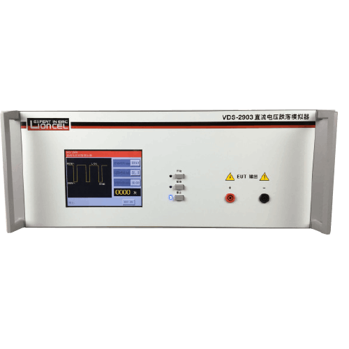
在進行Voltage Dips, Short Interruptions and Voltage Variations Immunity Tests時,測試人員會使用具有可調節電壓和頻率的電源發生器產生一系列的瞬態電壓干擾信號,包括電壓降、短暫斷電和電壓變化等,並將這些信號傳遞到待測設備上。待測設備會在瞬態電壓干擾信號下進行操作,而測試人員會監測設備是否能夠正常運行。
在 Voltage Dips, Short Interruptions and Voltage Variations Immunity Tests 過程中,測試人員會使用不同的測試參數,例如電壓降的深度、短暫斷電的時間等。這些參數通常是由相關的EMC標準和規定所指定的。
通過 Voltage Dips, Short Interruptions and Voltage Variations Immunity Tests,可以確定設備能夠承受瞬態電壓干擾信號的強度和頻率範圍,以及設備在受到瞬態電壓干擾信號時是否能夠正常運行。這些測試可以幫助設計人員和製造商確保其產品符合相關的EMC標準和規定。
總之,Voltage Dips, Short Interruptions and Voltage Variations Immunity Tests是一種用於評估電子設備對瞬態電壓干擾的測試方法,通過模擬瞬態電壓干擾信號來確定設備能夠承受瞬態電壓干擾信號的強度和頻率範圍,以及設備在受到瞬態電壓干擾信號時是否能夠正常運行,以確保設備符合相關的EMC標準和規定。
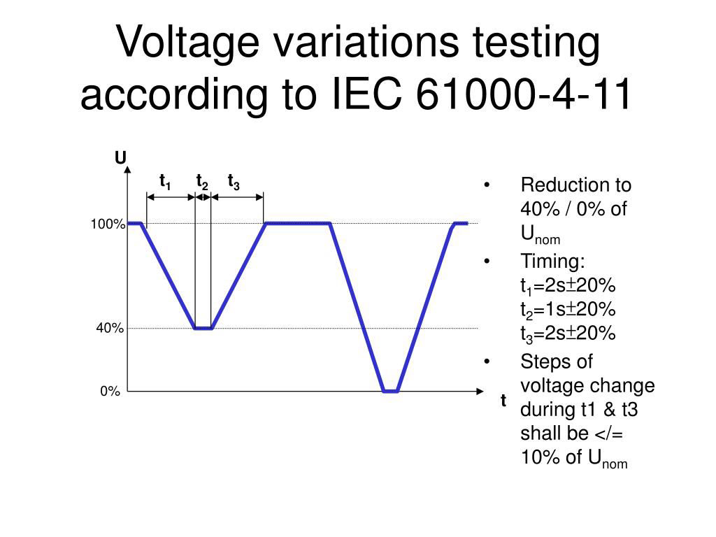
IEC 61000-4-11 defines the immunity test methods and range of preferred test levels for electrical and electronic equipment connected to low-voltage power supply networks for voltage dips, short interruptions, and voltage variations.
This standard applies to electrical and electronic equipment having a rated input current not exceeding 16 A per phase, for connection to 50 Hz or 60 Hz A.C. networks.
It does not apply to electrical and electronic equipment for connection to 400 Hz A.C. networks. Tests for these networks will be covered by future IEC standards.
The object of this standard is to establish a common reference for evaluating the immunity of electrical and electronic equipment when subjected to voltage dips, short interruptions and voltage variations.
This second edition cancels and replaces the first edition published in 1994 and its amendment 1 (2000). This second edition constitutes a technical revision in which:
1. preferred test values and durations have been added for the different environment classes;
2. the tests for the three-phase systems have been specified.
It has the status of a Basic EMC Publication in accordance with IEC Guide 107.
Dips and Interrupts Background
Dips and interrupts can occur on the AC power mains as a result of a fault in the distribution system such as an open circuit breaker or a sudden large load being turned on in the immediate vicinity. A power distribution system fault can cause a switch in the distribution grid to open and close a number of times, resulting in multiple interrupts to electrical and electronic equipment.
Electronic products are tested for immunity to dips and interrupts to insure their continued reliable operation if subjected to dips and/or interrupts on the AC power mains. The European Union’s EMC Directive mandates dips and interrupts testing for virtually all electrical and electronic products as a condition for obtaining the CE Mark before shipping products to member states of the European Union.
Applicable Standards
Generic Immunity Standards, Product Standards and Product Family Standards require that dip and interrupt tests be performed in accordance with Basic EMC Standards: IEC 61000-4-11 and EN 61000-4-11. Thermo KeyTek’s Application Note, “EMC Standards Overview,” provides an overview of European Standards for electromagnetic compatibility, describes how the Standards relate to one another, and lists sources for procuring copyrighted documents.
1 IEC 61000-4-11 and EN 61000-4-11 are virtually identical standards.
Basic EMC Standard
The Basic EMC Standard for Dips and Interrupts defines methods of generating consistently reproducible electrical dips and interrupts for test purposes. They specify characteristics of the AC mains to the EUT such as peak inrush current, transition times and durations. While the Basic EMC Standard specifies how to perform Dips and Interrupts testing, the Generic, Product and Product Family Standards specify the test levels and pass/fail Performance Criteria.
Peak Inrush Current
IEC 61000-4-11 requires the simulator be capable of supplying peak inrush currents of up to 500A for 220V to 240V mains, and up to 250A for 100V to 120V mains. Additionally, the Standard requires this capability be measured using a bridge rectifier connected via a switch to a discharged 1700µF capacitor. The parallel discharge resistance should be chosen to allow several RC time constants between tests. An example in Annex A (normative) uses a 10k ohm resistance, providing a time constant of 17 s, “…so that a wait of 1.5 to 2 minutes should be used between inrush drive capability tests.”
The test for inrush current is performed by switching the generator from 0% to 100% at both 90Þ and 270Þ to insure sufficient peak inrush current drive capability for both polarities.
Waveform Verification
IEC 61000-4-11 requires that the simulator output be verified periodically. For Dip and Interrupt test simulators, it is necessary to verify the voltage transition levels, transition times to 100%, and the inrush current capability. Most modern oscilloscopes are capable of observing the voltage levels and transition times. For verifying the inrush current, a bridge rectifier, suitably rated 1700µF capacitor and appropriate current transformer are required.
Test Execution
According to IEC 61000-4-11, tests must be performed in compliance with the manufacturer’s test plan, which shall specify:
• Input power of the EUT
• Performance Criteria
• Operation modes of the EUT
• Test set-up description
• Type of designation of the EUT
• Information on possible connections, cables, peripherals, etc. After each group of tests, a complete functional test must be performed.