Radiated Immunity 測試是一種用於評估電子設備在強大的電磁場環境下的表現的測試方法。該測試旨在確定設備是否能夠在真實的操作環境中正常運行,而不受到電磁場的影響。
在進行 Radiated Immunity 測試時,測試人員會在一個被控制的環境中產生一個強大的電磁場。這個電磁場可以由一個類似天線的設備產生。然後,測試人員會將設備放置在這個電磁場中,以評估設備對這個電磁場的抗干擾能力。
在測試過程中,測試人員會逐漸增加電磁場的強度,直到發現設備出現了故障或不能正常運行為止。這個故障電平被稱為設備的耐受性閾值(Threshold Level)。
Radiated Immunity 測試的目的是確定設備能夠在強電磁場的干擾下正常運行。這些測試可以幫助設計人員和製造商確保其產品符合相關的 EMC 標準和規定。在某些情況下,這些測試也可以幫助決定設備的操作範圍和條件。
總之,Radiated Immunity 測試是一種用於評估電子設備在強電磁場環境下的表現的測試方法,可以用於確定設備是否符合相關的 EMC 標準和規定,以及幫助確定設備的操作範圍和條件。
This standard is part of a set of basic EMC standards that outline test procedures that must be successfully accomplished before products can be sold. The object of this particular standard is to establish a common reference of a product or device to radiated RF immunity cause by any emitting source. Products must be designed and tested to insure that they are immune to both intentional transmitters, such as walkie talkies and cell phones, and unintentional RF emitting devices like electric motors and welders. There are 4 basic test levels which a product must withstand in order to pass this test:
Test Level Field Strength
1 1 V/m
2 3 V/m
3 10 V/m
4 30 V/m
This standard does not suggest that a single test level is applicable over the entire frequency range, and should be tested for the appropriate test level for each frequency range. Testing for general purpose RF emissions covers the 80MHz to 1000MHz frequency range, and should be performed without any gaps. For digital radio telephones and other higher frequency devices, tests should be performed in the 800MHz to 960MHz and 1.4GHz to 6.0GHz frequency ranges. Tests in these ranges do not need to be applied continuously over the entire range, and the ranges may be limited to specific frequencies for compliance with specific operating bands in the country the product will be sold in.
There are four major changes that were made to this standard in the third version to better measure immunity at higher frequency ranges which are now more commonly present. First and most importantly, the new harmonic distortion requirement of the test setup must be better than -6dBc. This is to minimize distortion at higher frequency ranges. Also, a linearity check must be performed before testing to ensure that the RF amplifier used is not operating in compression. Third, the frequency range was extended up to 6GHz as a result of increased use of these bands by newer electronic devices. Lastly, there is a change to the test table material requirement. This was done because materials like wood can become reflective when exposed to higher frequencies.
Test Equipment Needed
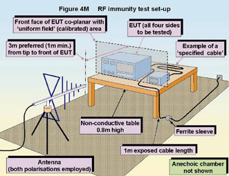
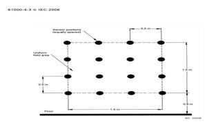
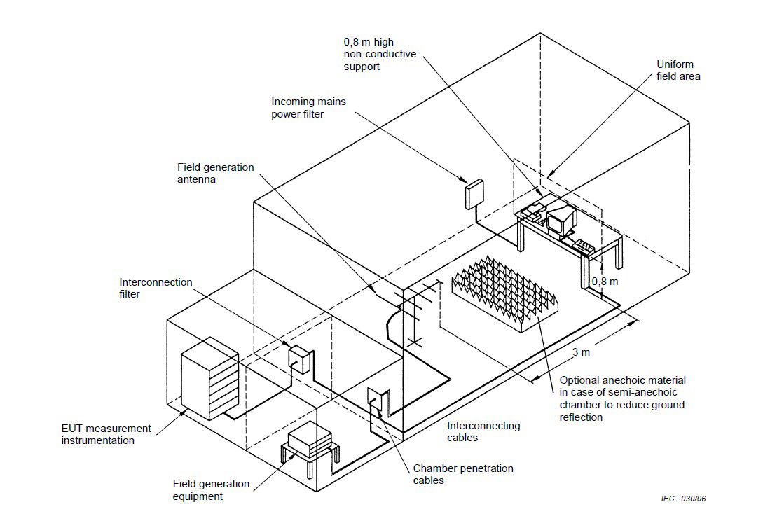
Anechoic Chamber – The chamber must be big enough to house a uniform field with sufficient dimensions to cover the entire EUT.
EMI Filters – Though not always necessary, use of filters should not add any additional resonance effects during the test
RF Signal generator(s) – The use of a signal generator must be able to cover the frequency being tested, and multiple generators may be needed if multiple frequencies are being tested. It must also be amplitude modulated by a 1 kHz sine wave with a modulation depth of 80%. Also, the generator must have a manual control or be programmable with frequency dependent step sizes or dwell times.
Power Amplifiers – this is used to amplify the signal and provide antenna drive to the necessary field level. Harmonics must be at least 6dB below the fundamental frequency
Field Generating Antennas – These can be either bi-conical, log periodic, horn or any other linearly polarized antenna system
Isotropic Field Sensor – This must have adequate immunity to the field strength being measured and use a fiber optic link to an indicator outside of the chamber
Equipment to record power levels – usually a computer system
Test Facility
The tests performed to conform to this standard must be done in a shielded enclosure. This is because many countries have laws prohibiting interference to radio communications, and this can arise if not properly shielded. The facility must also have a barrier between the EUT and the test instruments. This will minimize distortion and limit errors in results. Interconnecting wiring that can penetrate the shielded enclosure is used, and this wiring must properly attenuate conducted and radiated emission as well as preserve the integrity of the EUT signal and power responses. It should be noted that anechoic chambers are less effective at lower frequencies.